Geotechnical News • March 2012
27
GEOTECHNICAL INSTRUMENTATION NEWS
Remote monitoring of deformation using Terrestrial
Laser Scanning (TLS or Terrestrial LiDAR)
Matthew J. Lato
Principle of operation
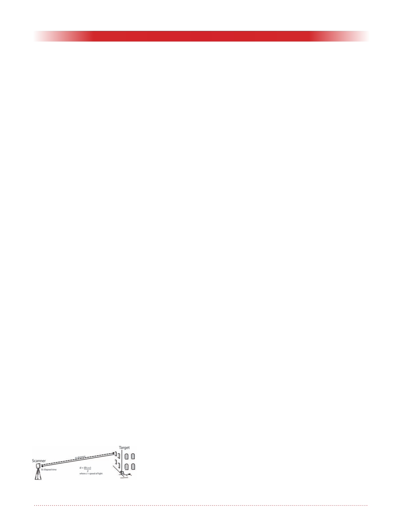
Terrestrial Laser Scanning (TLS) is a
remote measurement technique that
employs Light Detection and Ranging
(LiDAR) technology. TLS calculates
the distance between the scanner and
the target by measuring the time delay
between an emitted laser beam and the
reflected signal (illustrated in Figure
1). This is a similar technology to total
stations; however, the laser is roboti-
cally rotated through the scanners field
of view measuring up to one millions
points per second. The georeferencing
of TLS data is done through placement
of targets in the scene, typically flat
circles are used. The targets are also
used for measuring deformation at
specific locations.
Main fields of application
TLS is used for geotechnical monitor-
ing of tunnels (during construction
and post construction degradation);
rockcuts along transportation cor-
ridors; construction (piles, shoring,
etc.); landslides; dams; and building
deformation. Non-geotechnical appli-
cations include forensics; archeology;
and architecture.
Accuracy and pixel
resolution
TLS accuracy is determined by sys-
tematic and random error. Systematic
error is governed by range error and
angular error. Range error is error in
the measurement of distance between
the scanner and the target. Angular
error is the error in the positioning of
the scanners mirrors. Systematic errors
translates to an accuracy of +/- 5 mm
at 25 m, to +/- 30 mm at 1000 m
.
Random errors are in relation to the
incidence angle between the scanner
and target, as well as the reflectivity
of the target. Random errors affect the
precision of the measurement, which
is variable, generally 0 – 10 mm,
regardless of distance.
Pixel resolution of TLS equipment
is based on the distance between the
target and the scanner, as well as the
type of scanner. This value can be as
high as 5 mm at 25 m. However, due
to beam divergence, the pixel spacing
in the point cloud and the sampling
resolution must be evaluated for every
project.
Main advantages
Using TLS for deformation monitor-
ing is advantageous for many reasons
relating to data collection, process-
ing flexibility, and presentation of
results. TLS is an extremely fast,
accurate, non-destructive technology.
Data collection can be integrated with
construction projects or implemented
in remote regions. Processing options
are diverse, including investigating
individual TLS models for geometry,
comparison to CAD, and temporal
modeling over time. As well, the high
resolution nature of the data enables
realistic images and models for report-
ing of results.
Main limitations
TLS is an emerging technology with
variable equipment and processing
options. Users must be aware of their
options and the limitations of each
system. As well, it is essential that
data be collected properly, without
occlusion (shadowed regions) and
processed in a manner that preserves
accuracy.
Future challenges
There are three main challenges for
using TLS in geotechnical monitoring:
data format, processing standards, and
timely collection of data. Data formats
are critical in an industry that employs
various TLS technologies, each of
which uses its own binary format to
reduce file size. A standard format will
ensure that data collected today will
be processable on future computers.
For example, airborne LiDAR (ALS)
data is stored in the industry-approved
LAS
format. No such format exists for
TLS data. The use of TLS for monitor-
ing is generally performed on an on
demand basis; there exist no general
guidelines for data manipulation,
analysis, or presentation of results.
For TLS technologies to be adopted,
this must be addressed. Finally, TLS is
viewed as a costly tool and therefore
is generally used once site conditions
have deteriorated. This is a challenge
for achieving the optimal monitoring
results because a baseline cannot be
established. To achieve the best results
from TLS, data must be collected
before problems arise.
Some commercial sources
• Applied Precision: Mississauga,
Canada,
.
com, +1 905-501-9988
• Norwegian Geotechnical Institute,
Norway,
, +47 414 93
753
• Precitech AB, Sweden,
+46 31 762 54 00
Matthew J. Lato
Engineer, Norwegian Geotechnical
Institute, Oslo, Norway,
T: +47-465-42-970,
E:
Figure 1. Operating schematic of a
TLS scanner.


