32
Geotechnical News • March 2012
GROUNDWATER
Influence of element size in numerical studies of seepage:
Small-scale details
Robert P. Chapuis
Many of us use numerical codes to
study groundwater seepage within
aquifers and aquitards, and often to
solve groundwater engineering prob-
lems. A previous paper (Chapuis 2010)
examined the influence of element size
on numerical result for large-scale or
regional studies. It was shown that
different grid sizes provide different
solutions, the convergence towards
a correct solution depending on the
mesh size. Both convergence and
mesh size need to be studied methodi-
cally.
One of its conclusions was that all
geometric details should be modelled
as accurately as possible, especially
at places where any sought function
(hydraulic head, gradient, velocity,
etc.) reaches a local maximum or min-
imum. The present paper studies two
examples of small scale details and
how the numerical results are modified
by the mesh size for the details. The
two examples are: (1) seepage below
a partial cut-off wall, and (2) seepage
towards a pumping well in an ideal
confined aquifer.
First example: dam and
partial cut-off wall
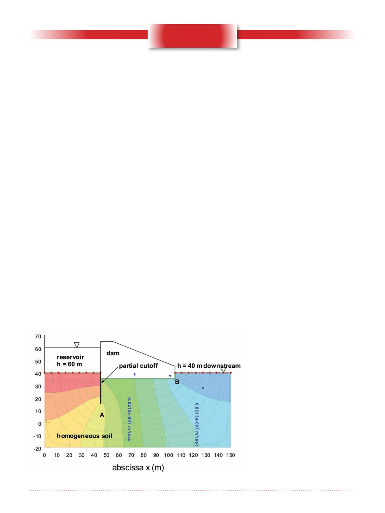
The problem geometry appears in
Figure 1, with the flow net for one
numerical grid. Output data relevant
for this engineering problem include
(1) the leakage rate through the dam
foundation
Q
(m
3
/m/s), (2) the risk of
soil internal erosion at the toe of the
cut-off wall, and thus the maximum
value of the hydraulic gradient here,
and (3) the maximum exit gradient
at the downstream side of the dam,
which must be less than 0.200 or
0.167 (1/5 or 1/6) for safety require-
ments (Chapuis 2009).
The finite element code Seep/W (Geo-
slope International 2003; 2007), an
older version of which has passed a
battery of tests (Chapuis et al. 2001),
is used here. This code uses the soil
characteristic functions, K(
u
w
) and
q
(
u
w
), in which
u
w
is the pore water
pressure, K(
u
w
) is the hydraulic
conductivity function, and
q
(
u
w
) is the
volumetric water content function. The
generalized equation of Darcy (1856)
for seepage, and Richards (1931) for
mass conservation, are solved numeri-
cally as
u
w
-based equations. The code
can find complete solutions for satu-
rated and unsaturated seepage. Once
the numerical analysis is completed,
the code provides equipotentials, flow
lines and flow rates through previously
defined surfaces.
Several grids are considered, start-
ing as always from the simple to the
complex or from the coarse to the
most detailed. The following output
data were obtained using the 2007
most recent version of the code. The
uniform meshes had sizes of 10, 5,
2, 1, and 0.5 m whereas the refined
meshes started with a 0.5 m uniform
meshing before making a refinement,
at the toe of the cut-off wall, of 10,
5, 2 and 1 cm. The coarsest uniform
mesh size was 10 m. In fact, since
the cut-off wall has a width of 0.5 m,
the automatic mesh generator drew
elements 10 m high and 0.5 m wide
under the cut-off, without giving a
Figure 1. Partial cut-off wall: flownet in the dam foundation.


