42
Geotechnical News • December 2019
THE GROUT LINE
pictures in fig. 8) of the discovered
columns) and to set up the operational
parameters (flow rate and pressure of
grout and air, uplift velocity, rotational
speed) after the treatment energy pro-
cedure (Tornaghi et al. 2004).
In order to allow a more regular high
pressure injection during the uplift
phase, even in presence of boulders,
each column execution was preceded
by a predrilling, carried out 1 m down
into the bedrock, by means of a dedi-
cated drilling unit.
Some preliminary pre-drillings along
the columns’ alignment (for the cof-
ferdam as well as for the impervious
curtain) were initially made, in order
to detect the bedrock level and hence
to draw an accurate profile of the allu-
vial deposit base.
The geometry of the treatment
involved the execution of inclined
columns at the two ends of the curtain,
with drillings made with angles up to
43° from the vertical.
During the treatment of the cofferdam,
the steel pipe reinforcement was usu-
ally inserted in the hole made for the
jet grouting.
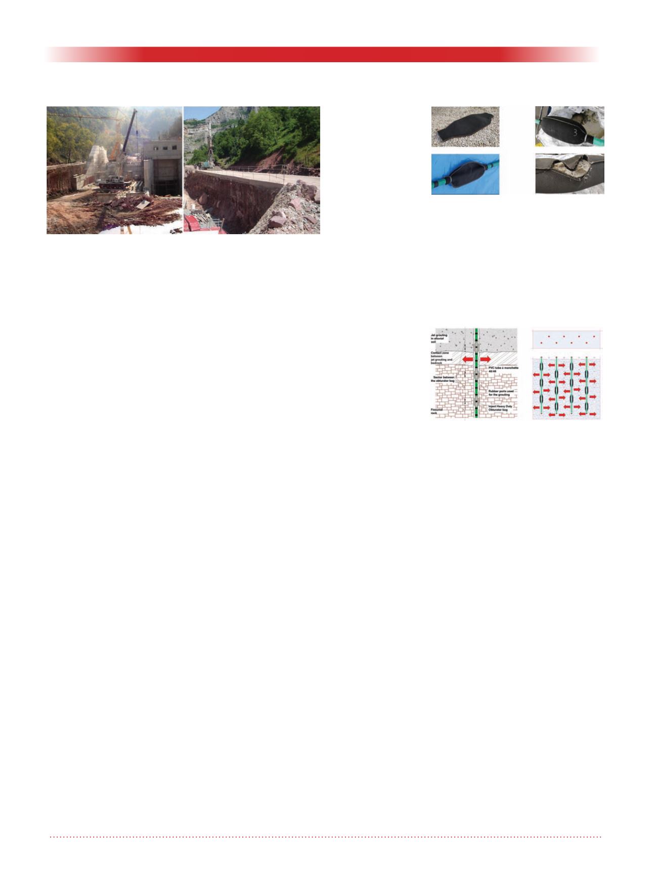
The effect of the treatment was suc-
cessfully tested during the excavation
for the plant construction. The picture
in fig. 9 shows on the left the jet
grouted wall that separates the
riverbed from the area of the site
for the power house and the gates
building. No significant water income
from the waterproofed embankment
occurred.
On the right –
The road on the
crown of the
embankment,
used for the site
traffic
This allowed for
completion of
all the activities
for the power
plant construc-
tion (from the
embankment con-
struction to the test on the turbine) in
18 months without any interruption. In
case of seasonal interruption (without
the waterproofing of the cofferdam),
6 additional months should have been
considered. Until today, during the
works for the five plants completed,
only on one occasion the river has
overflowed the embankment, causing
a flood that interrupted the works. The
site was evacuated on time, thus limit-
ing the damages. Two months were
necessary for restoring the yard.
Rock grouting
The treatment of the rock for the
impervious curtain was carried out
using the MPSP (Multiple Packer
Sleeve Pipe) system. After the hole
was drilled, a
Ø
1”1/2 PVC TAM
pipe (40/48 mm inner/outer diameter)
was installed. The TAM pipe was
equipped, every 3 to 5 meters, with
several Heavy Duty Obturator Bags,
made in polypropylene geotextile and
mounted on one or two sleeves. The
bags were initially folded and fixed to
the pipe at the ends by a metallic tie
(see fig. 10). The tube was centred by
means of plastic collars.
Once the pipe was in place, the bags
were filled with injected cement grout
(ratio W/C=0.6:1) by a double packer
lowered to one of the correspondent
sleeves, and finally sealing the annular
space between the plastic pipe and
the borehole. Under the pressure of
the injection, the cement of the grout
separated from the water, being the
latter ejected per seepage through the
geotextile. As a result, the hole was
divided into several stages by means
of the tough sealings obtained inject-
ing each obturator bag; a curing time
of 18-24 hours were sufficient for the
aim (see fig. 11).
The grouting of each stage was then
made with the conventional MPSP
injection procedure. The double
packer was placed astride one of the
sleeves of the deeper sector, but in this
case no plastic sheath was necessary.
In fact, the grout filled initially the
annular void between the pipe and the
borehole, and then it flushed into the
fissures intercepted by the hole stage.
The injection was then carried out
following the prescribed rules for
the rock treatment. The curtain was
formed by two alignments of TAMs,
spaced 1.50 m (5ft) and with interaxis
of 1.50 m (5ft) between the boreholes.
In a first phase primary pipes were
drilled and injected; then the second-
ary pipes phase followed (fig. 12).
Along the earth dam axes the holes
were drilled passing through the jet
grouted columns.
The obturator bags were installed
every 3 to 5 m (10 to 16 ft) in the pipe
stretch into the rock to be treated.
Another bag was mounted about 1 m
Figure 9: On the left - Works in progress with the jet
grouting wall protection from the river bed.
Figure 10: Folded and injected
obturator bags mounted astride a
manchette.
Figure 11: Scheme of the MPSP
system grouting.


