Geotechnical News• December 2019
41
THE GROUT LINE
The setup of the geometry of the
three-dimensional model was per-
formed starting from the implementa-
tion of the 3D DTM (Digital Terrain
Model) of the area and assembling the
geometry of the dam structure accord-
ing to the proper design. Then, based
on the hydraulic properties of the
rocks and the soils affected by the dam
construction, which have been derived
from the results of the investigations
available, and the boundary conditions
assigned to the model, the continuity
equation governing the water seep-
age in the soil domain was integrated
in order to derive the values of the
hydraulic head for each node and
the values of the pore water pressure
accordingly. The main features of the
seepage regime consequent to the con-
struction of the dam were calculated in
order to design the impervious curtain
under the weir and the dam founda-
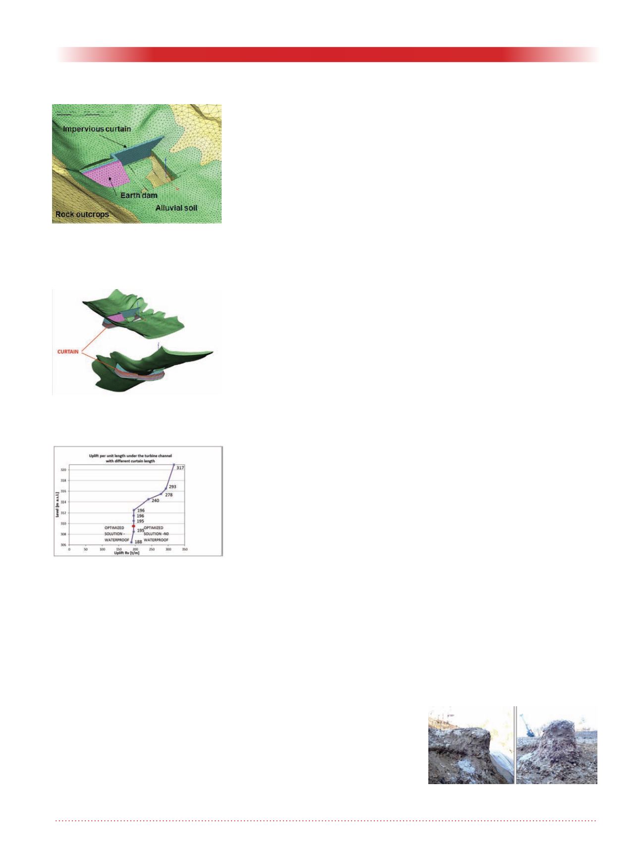
tion. A sensitivity analysis was carried
out taking into account different
values for the size of the impervious
curtain to assess the optimal length of
the same structure according to a cost-
effective solution (fig. 6 and fig. 7).
The impervious curtain
For all the plants the deepest excava-
tion level is placed in the area of the
power house, where the bedrock is
always uncovered. Hence the impervi-
ous curtain required to treat the most
surficial rock mass, all along the align-
ment, the coarse surficial deposit on
the sides of the section, and the earth
dam core.
The investigations showed that the
upper part of the bedrock was very
weathered with a thickness highly fis-
sured zone variable from 2 m to 5-6 m
and presenting very low RQD values.
The permeability values, measured
with Lugeon test, vary normally
between 3 and 50 Lugeon Units (UL),
and in several cases they can rise up
to 600 UL. According to the design
model, the target of the treatment for
the curtain was to not exceed 3 UL.
The alluvial formations were com-
posed of gravel and sand, in some sites
including 15-30% of silty fraction;
boulders were detected in the zone of
the current riverbed and in the flood
plain side areas, but normally only in
a surficial position. The permeabil-
ity, measured with Lefranc test, gave
results between 10
-4
to 10
-6
m/s (m/s =
3.2 ft/s) : the target after the soil treat-
ment in those strata and in the earth
dam core was fixed at 1-5x10
-7
m/s.
For the execution of the impervious
curtain, it was decided to treat the
soil with two lines of double fluid jet
grouting columns
Ø
1.30 m (4 ft), and
to grout the rock with cement mixes.
The curtain was carried out after the
execution of the earth dam, and, usu-
ally (but not always, due to the main
works scheduling), after the cast of
the weir and power house foundation
plate.
The critical issues of this solution
were hence:
• the locally highly fractured rock
in the transition zone to the upper
alluvial deposit
• the possible weakness of the jet
grouting treatment at the bottom
of the columns, in correspondence
of the contact with the underlying
rock
• the contact zone between the
ground and the concrete founda-
tions of the weir and the power
house, because of the surficial
disturbance of the rock due to the
excavation (made with blasting or
with non-explosive agent) and of
the discontinuity with the concrete
casts that need to be properly
sealed.
In order to obtain a homogeneous
treatment in all those critical zones, it
was decided to perform the rock grout-
ing by means of the MPSP (multiple
packer sleeve pipes) placed into the
holes that crossed the jet grouted soil
or the concrete foundations. MPSP
was chosen to avoid the risk of losing
packers, and consequently holes, in
the highly fractured rock.
The Ground Treatments
Jet grouting
Jet grouting columns were executed
as first, using air and a water/cement
ratio W/C =1 for the grout, injected
with a pressure of 40 MPa (5.8 ksi).
At the beginning of the activities, a
trial field was executed in order to
evaluate the result of treatment (see
Figure 5: The 3D model mesh.
Figure 6: A detail of the curtain
elements.
Figure 7: Sensitivity analysis of the
curtain depth.
Figure 8: Jet grouting trial columns
executed at the start of the works.


