40
Geotechnical News • December 2019
THE GROUT LINE
Geotechnical investigation
The execution of several corings along
the main cross section of each barrage
allowed for reconstruction of the bed-
rock surface covered by the surficial
alluvial layer.
In each hole, permeability tests have
been carried out at different depths:
Lefranc tests into the alluvial soil
strata, Lugeon tests in the rock. Usu-
ally the corings put in evidence that
the upper part of the rock is rather
highly fractured. This information has
very often been confirmed and is bet-
ter proven by the Lugeon test results.
The cross section in Fig. 2 concerns
the plant of Lakatnik.
Power plant design
Each plant is composed by: the main
building that includes the intake chan-
nel, the turbine, the outlet channel, the
control hall; the weir with the gates;
the lateral earth dam (see fig. 1).
During the plant construction, an
earth embankment was built in order
to protect the front, the back and a
side site of the area from the river, as
shown in the following figure 3. The
embankment has been waterproofed
by executing, down to the bedrock
level, a line of temporary jet grouted
columns. This line of jet grouted col-
umns allowed for the execution of the
concrete structures and the installation
of the turbine and the electromechani-
cal devices regardless of the varia-
tion of the flow rate of the river: no
seasonal interruptions of the activities
were necessary.
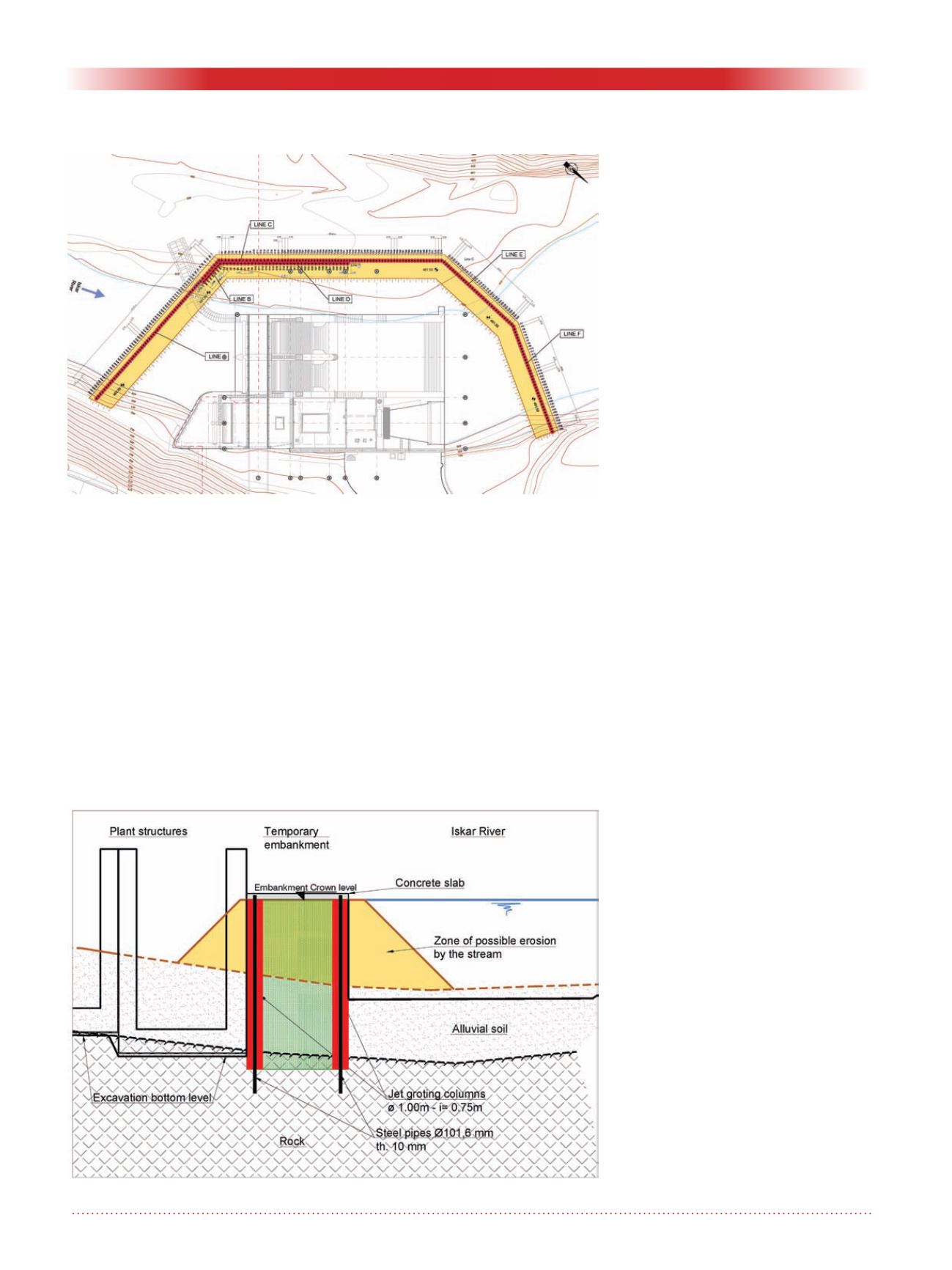
In some sites the plant lies in corre-
spondence of a narrow section of the
valley, so in order to guarantee the
necessary flowing section of the river,
the embankment was placed beside
the external alignment of the abut-
ment wall of the plant. In this case the
embankment has been considered as
a gravity structure, with two lateral
lines of jet grouting columns axially
reinforced with a steel pipe anchored
into the bedrock (see fig. 4).
The internal side of the embankment
has been excavated to uncover the jet
grouting columns; during the works
the grouted wall was protected with a
mesh of reinforced shot concrete, until
the cast of the abutment wall finally
covered the vertical surface. The
reinforcements were designed taking
into account that the water flow might
remove the slope of the embankment,
and considering the hydraulic load
applied to the remaining treated core
with the deeper level reachable during
the plant excavation. So the reinforced
double jet grouting sheet has a double
function: to assure the equilibrium of
the embankment and to protect it from
the erosion by the river water.
For each plant a FEM analysis of the
steady-state seepage process following
the construction of the dam and hence
the presence reservoir was carried out
by applying a three-dimensional finite
element code (Fig. 5).
Figure 3: Cofferdam as protection of the site during the activities in case of
river flood.
Figure 4: Cofferdam reinforced with jet grouting columns and steel pipes.


