Geotechnical News • March 2012
41
stresses imposed by the membrane on
the soil-structure comes down. The
resulting loss of shear strength is not
because of the pore pressure increases,
it is because of membrane interfer-
ence.
To clarify this important point I’ll
resort to a “
reductio ad absurdum
”
style of reasoning. Figure 15 shows
to the left, to honest scale, the space
required within the membrane to
accommodate a mass of uniform
spheres at their loosest packing
(e=0.91). In the centre and to the right,
the volume required by this same mass
of spheres is shown for their densest
packing (e=0.35). It is apparent that
changing from the loosest to the dens-
est packing (extreme contraction) must
involve an increase in the proportion
of the cell pressure conveyed to the
water, with obvious consequences to
the load bearing capacity of the soil
column.
The idea that pore water pressure
increases cause failure is simply
wrong-headed. In fact, in terms of
soil-structure stability, excess pore
water pressure is not intrinsically
a bad thing. But if it is changing in
magnitude then it is a clear indication
that the solid phase is trying to move
through the liquid phase, and that
things are not at rest. This is because
deformation of the soil-structure
results in the creation of pressures
in the void water, and those respon-
sive pressures act in a manner so as
to oppose the movement of the soil
particles. Essentially, the changes in
pore water pressure are an effort of the
system itself to rectify the situation; its
own attempt to prevent movement and
maintain the
status quo ante
.
In trying to visualize how the pore
pressure generation mechanism works
I found the analogy of a hydraulic
piston helpful. I try to imagine what
would be going on as a piston is being
pushed into a rather leaky cylinder.
Needless to say the piston is a particle
and the leaky cylinder is the saturated
soil-structure with drainage from a
natural boundary some distance away.
Now, if we leave the unreal “und-
rained” condition behind us, and look
instead at an apparatus which does a
fair job at representing soil behaviour
in a natural setting we may see if the
“leaky piston” helps. What I have in
mind is the laboratory consolidation
machine, or oedometer.
For simplicity let’s consider one-
way drainage from an impervious
solid base to an upper highly porous
platen. When the consolidation force
is applied to the platen, that force is
transferred entirely to the topmost
layer of particles, with the water
continuum carrying virtually none of
it. This is because, apart from having
very little shear strength to provide
bearing capacity, the water in physi-
cal contact with the porous platen
can escape through it with very little
resistance/effort. The soil-structure
responds to the load by contracting
into a more resistant intergranular
arrangement. This involves all the
particles moving towards the base,
and this relative motion between the
phases generates a pore water pressure
field which grows in magnitude, par-
ticle after particle, until the solid base
is encountered. At the base there can
be no particle movement and therefore
the pressure generation ends there.
This generation of a hydraulic gradi-
ent within the specimen creates the
required condition for seepage flow
(leakage) from it. As consolidation
progressed, and the soil-structure gets
stronger, the rate of movement slows
down, and with it, the generation of
pore pressure. Eventually, the time
comes when the soil-structure can
carry the newly applied load without
further movement, and consolidation
leakage ends at this moment.
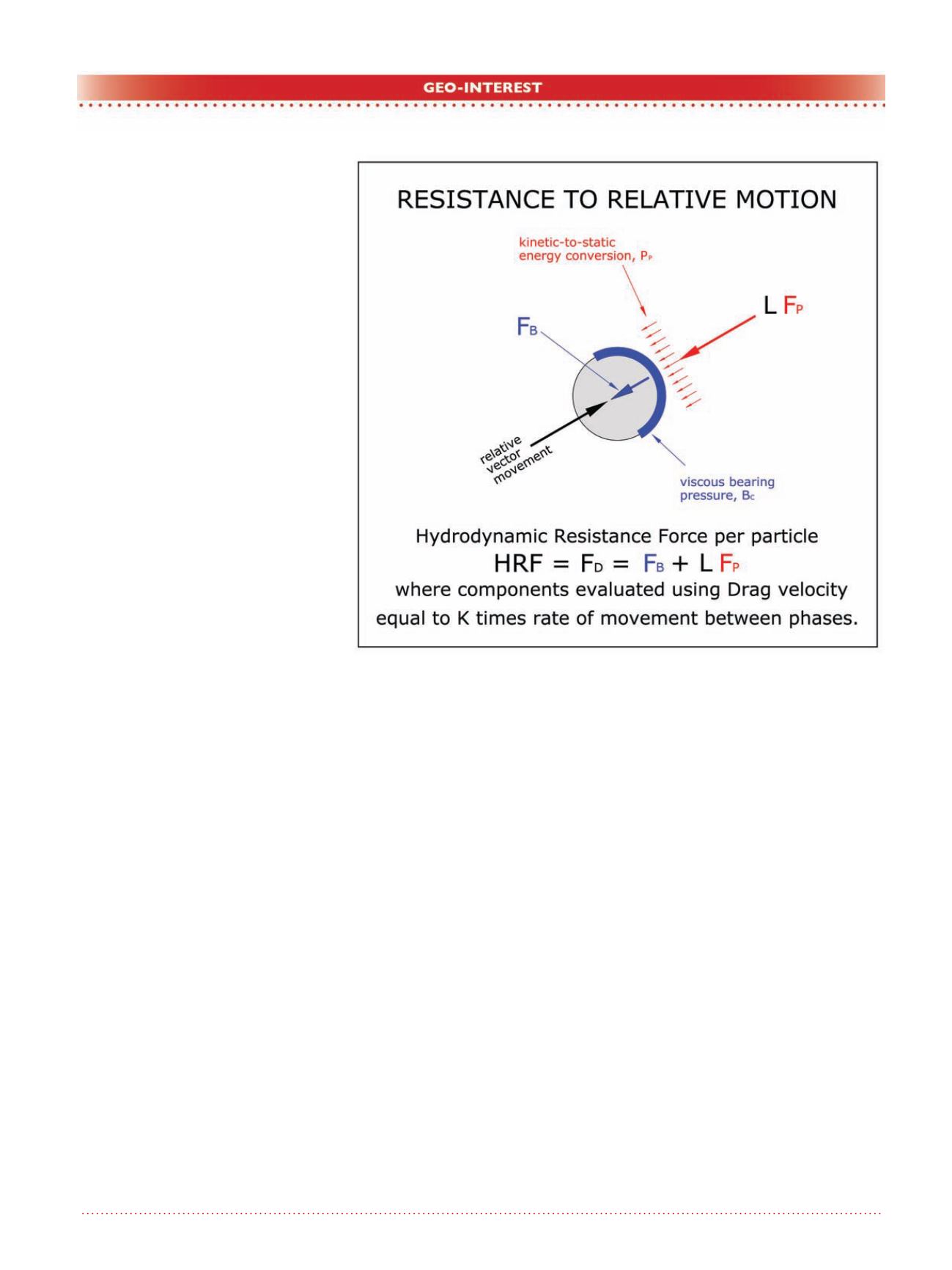
Calculating pore pressure
generation
Figure 16 illustrates the water forces
generated by relative motion between
Figure 16. Resistance to relative motion.


