42
Geotechnical News • March 2012
the phases of a soil-structure immersed
in water. As we are concerned here
only with hydrodynamic forces, no
effort is made to represent inter-parti-
cle forces on this schematic.
For a single particle, represented here
by a sphere, the Crowding Factor,
K is = 1. As discussed earlier, in the
case of soil aggregations K > 1, where
that value depends on particle sizes,
packing density, and fluid velocity.
Depicted here are the two compo-
nent forces, viscosity and pressure,
which together make up what I call
the Hydrodynamic Resistance Force
[HRF], and which I treat as the funda-
mental quantum of resistance offered
by each soil particle to soil-structure
deformation. It is here that the axiom
“pore pressure is the response to
movement, and not the cause of desta-
bilization” is most clearly expressed.
In order to perform the tedious calcu-
lations required for determining the
viscous drag and pore water pressures
generated in saturated non-cohesive
soil gradations, I wrote the computer
program EPWPGRAD. This program
is freely available from Geotechni-
cal News as a Fortran compiled DOS
executable file. Anyone who might
want the source code can write me.
The program works in the following
manner:
A.
The program requires the following
input:
• Soil gradation in terms of paired
mesh size and percentage of soil
passing that mesh for each of the
soil fractions. In other words, the
normal output determined during a
sieve analysis.
• Void ratio.
• Water temperature.
• Rate of relative motion between the
phases.
• Dimensions of a prismatic element
(rectangular box) of soil to be
assessed.
• Permeability of the soil if known;
if not known a built-in subroutine
PERMSOIL is used to estimate it.
B.
The program then goes about the
following routine:
• For each soil fraction, an aver-
age size is used to determine the
L-factor in this range. At the same
time, the number of individual
particles of this size within the soil
element is found/calculated.
• The permeability of the soil ele-
ment for this particular rate of
soil-structure movement is either
taken as user input, or calculated
by PERMSOIL.
• The hydraulic gradient across the
element is calculated from perme-
ability, and then used to evaluate
the element’s Seepage Force in the
direction of relative movement.
• By a process of iterating on the
void velocity, the unique overall
value for the Crowding Factor,
K, is found which would make
the total Drag Force across the
element numerically equal to the
Seepage Force that would prevail
for that same element of soil if
it were subjected/exposed to the
velocity of movement.
• The magnitudes of the two com-
ponents of HRF are calculated
for each soil fraction using the L
for that size, and the common K
for the aggregation. By summing
these components for each and
every particle within the soil ele-
ment the total force exerted against
the upstream face of that rectangu-
lar prism is arrived at.
• Energy and pressure gradients
across the element in the direction
of solid phase translation are then
readily available as part of the
program output.
As a point of interest, PERMSOIL
goes about estimating soil permeabil-
ity (hydraulic conductivity) in the fol-
lowing way. It takes as input the void
ratio, particle size distribution, and
water velocity being currently used in
the parent/main program. It deter-
mines for itself the fluid (in this case,
water) viscosity from the temperature
given.
It uses the J.S. Kozeny (1931) inspired
technique whereby an equivalent pipe
diameter can be assigned to a particu-
lar soil aggregation. He realized, quite
brilliantly, that this could be justi-
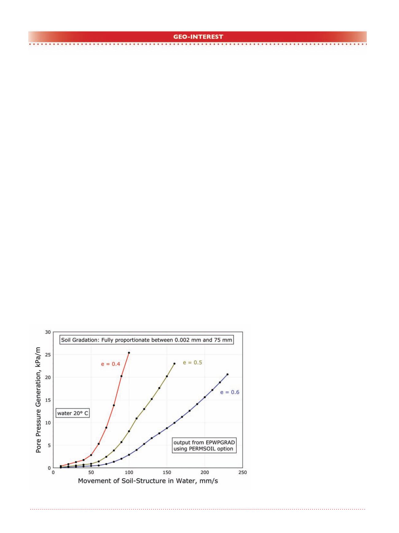
Figure 17. Pore pressure generation v. soil-water relative motion.


