46
Geotechnical News • December 2015
THE GROUT LINE
Provided that the limiting grout pres-
sures are not exceeded, the aim should
be to pump as quickly as practicable.
The GIN technique ensures that the
limiting pressure is progressively
reduced as the total injected volume
increases, and this limit is defined and
enforced by the GIN boundary curve.
It is prudent to limit the injection
rate over the first 15-50 L to avoid
immediately reaching the maximum
limit pressure, and modern control
measures allow for an injection rate
of, for example, 300 L per hour until
this volume has been placed. There-
after, the pump can be programmed
to seamlessly and automatically
increase injection rate up to its practi-
cal maximum, typically in the range
1’000-1’200 L per hour. This injection
rate should ideally be constant for all
injections, and each injection will con-
tinue at this rate until the plot of the
GIN value P x V approaches to within
approximately 1 bar below the GIN
boundary curve.
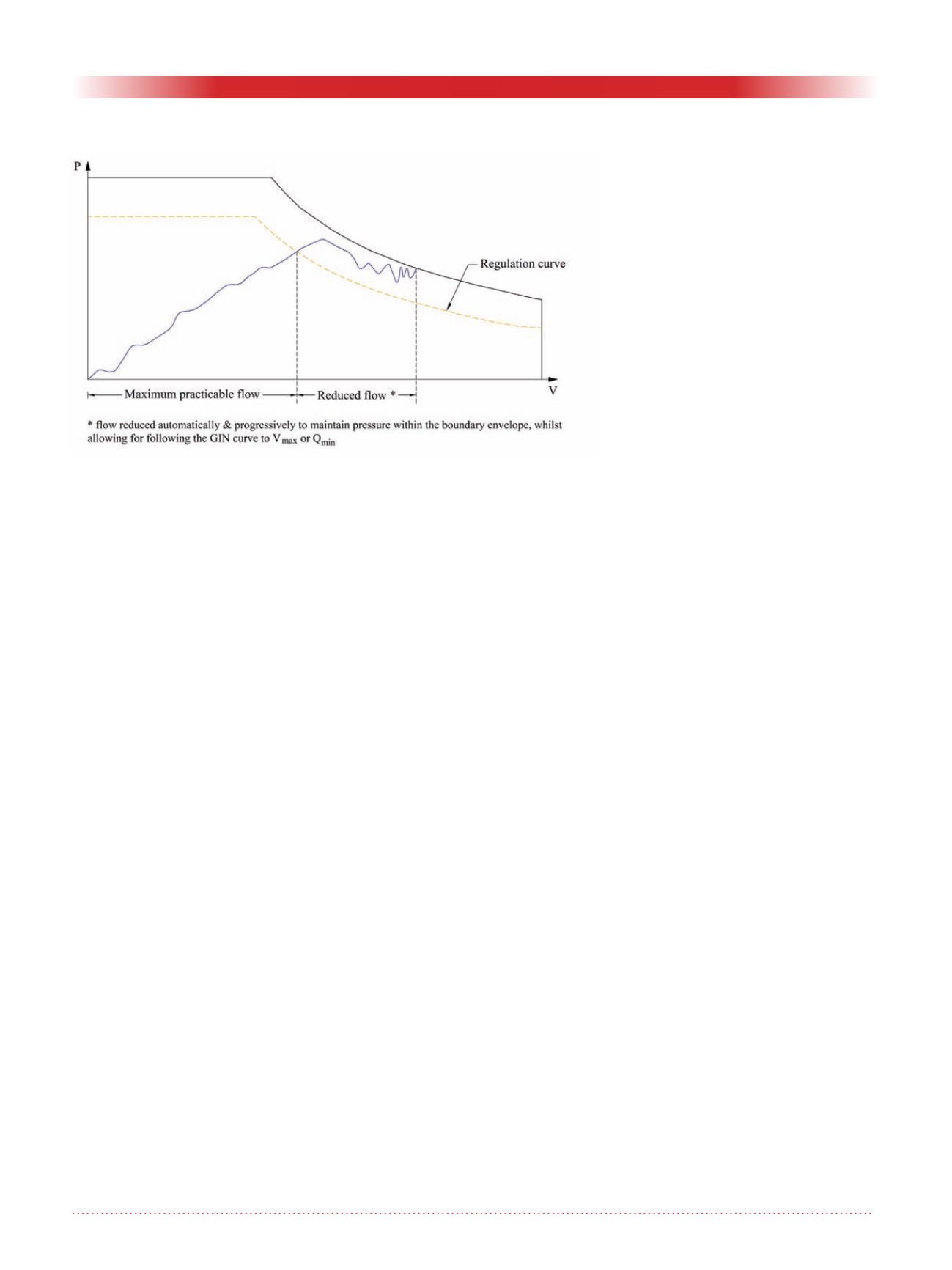
Practical experience has shown that
it is convenient to define a certain
regulation zone, when approaching
the GIN curve, for which a reduced
flow rate is imposed. As shown in
Figure 5, this zone is bounded by the
GIN curve itself and by a parallel
regulation curve typically at around
1-2 bars below the GIN value. Within
the regulation zone the pump flow
rate varies automatically according to
the cumulative grout volume and the
rock conditions, to maintain the GIN
plot within the regulation zone until
the injection terminates on minimum
flow or maximum volume. The path
of the GIN plot and the point at which
the GIN plot intersects the boundary
curve will be dependent upon the mix,
the pump injection rate, and the rock
characteristics. Once the cumulative
volume injected reaches the target vol-
ume for the stage, or the pump reaches
its minimum practicable and/or
economic pumping rate, the injection
terminates automatically. The target
volume and the minimum flow rate are
all pre-set into the software and cannot
be accidentally exceeded.
Once automatic regulation com-
mences, limiting the injection rate,
for low grout quantities, for too long
a time in this regulation zone, would
make the grouting works unneces-
sarily complicated and uneconomic.
There are mainly two options for the
termination criteria – either continue
grouting at a reducing flow rate until
the flow rate reduces to a pre-deter-
mined rate (somewhat equivalent to a
classical ‘refusal’ criteria), or the GIN
curve is followed until the previously
defined maximum volume is reached.
Applying the same criteria to every
single injection ensures that the
graphical plot for each injection can
be compared with that of every other
injection, and can provide a great deal
of information about progress and suc-
cess of the individual injection and the
progress of the works. It also, together
with the constant GIN value and mix
characteristics, adds greatly to the sub-
stance and accuracy of any numerical
analyses.
A key element of this visual inspection
is to see on completion of the injec-
tion whether the full target volume
has been injected, or whether the
injection is terminated too early. The
grouting engineer can see at a glance
what percentage of the target volume
has not been placed, and, can make a
judgement as to whether this is due
to improving rock conditions and
reduced transmissivity, or whether
the grout mix is inappropriate for the
formation, and it allows him to see
whether the GIN value is appropriate
or not. If he has any concerns on these
issues then, of course, he must be pre-
pared to modify the parameter accord-
ingly. However, this should ideally
be done for all remaining boreholes.
Varying the injection parameters for
each individual stage renders realistic
and systematic analyses of the results
extremely difficult, and prevents the
application of some very valuable
comparative analyses.
To avoid such an unnecessary com-
plication of the grouting process, it is
advisable, in the early stages of the
project, to immediately drop back
and carry out one or two secondary
injections after the first 3-4 primary
holes have been completed, to verify
that the assumptions made in terms of
target grout volume, GIN value, and
the optimum injection parameters, are
correct. The parameters should then,
if required, be modified at this early
stage and maintained unchanged wher-
ever possible for the remainder of the
works to keep the grouting works as
clear and manageable as possible.
Figure 5. Flow Regulation during the grouting process.


