Geotechnical News • December 2015
47
THE GROUT LINE
Minimum flow rate
The minimum flow rate set for the
injection should be a pragmatic deci-
sion based upon the characteristics of
the pump, technical and cost efficiency
considerations, and understanding of
the gel and set times of the selected
grout, and especially upon examina-
tion of the GIN curve and the implied
injection pressures at the point on
the curve where the maximum target
volume has been placed. If, at the
maximum target volume, either the
minimum flow rate defined by the GIN
curve is below the minimum desirable
injection rate, or the injection pressure
is too low for accurate regulation then
the design GIN value may have to be
increased accordingly.
These considerations need to take
into account the experience of the
grouting engineer in similar rock
conditions and with the character-
istics of the equipment being used.
There is no technical or commercial
advantage in continuing the injection
to a point where any further minimal
improvement in the rock condition is
not justified by the cost of continuing
injection, or beyond the point at which
there is a risk of grout line blockage or
inefficient injection due to a change in
the rheology of the grout mix.
Successful completion of grouting
Decision for additional boreholes
In accordance with the rock mass
conditions and project requirements,
grouting might be systematically
executed from primary or second-
ary boreholes, depending on the hole
spacing. The decision for additional,
i.e. tertiary or quaternary boreholes is
then based on the final grouting pres-
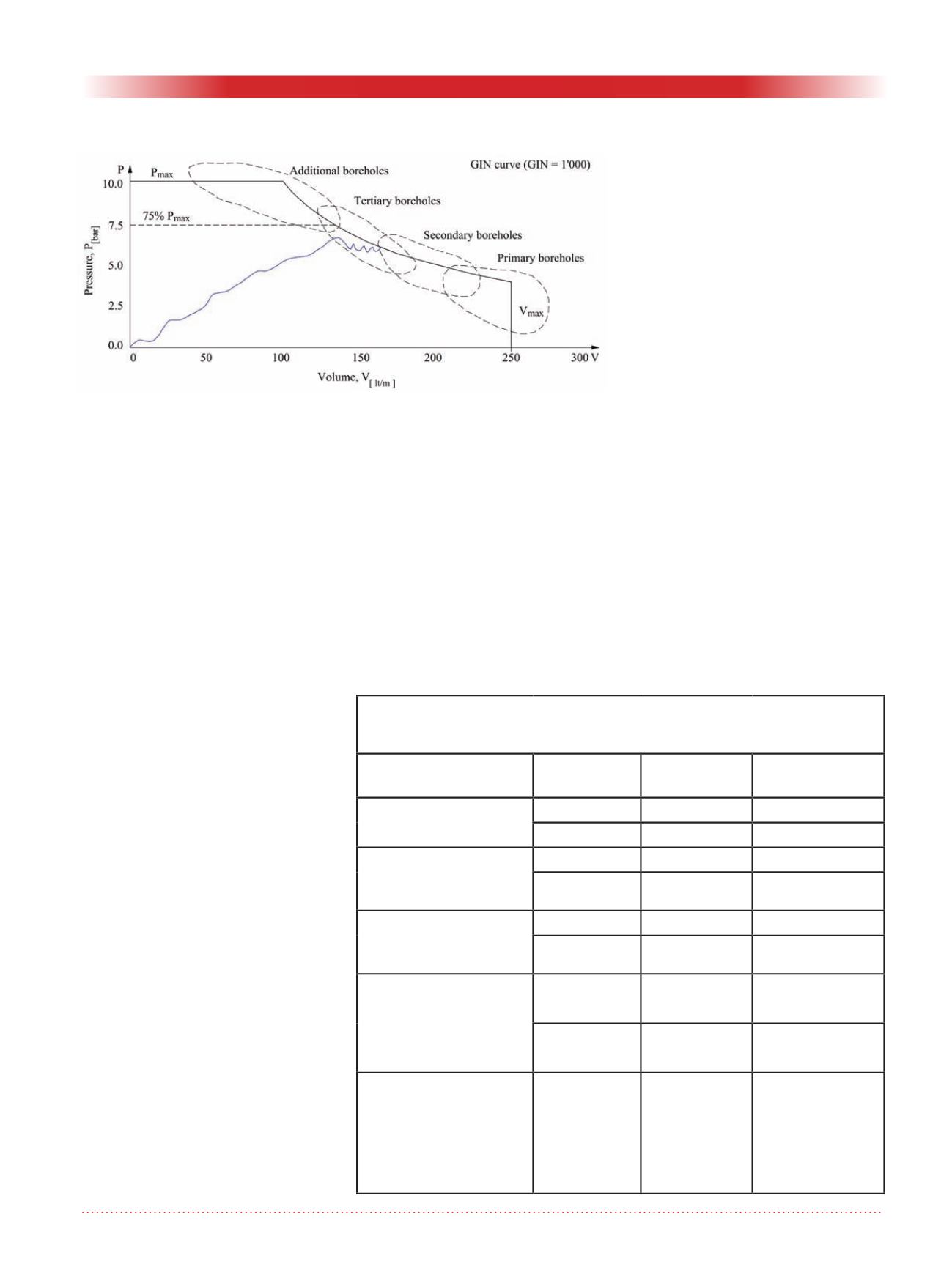
sure reached. According to the GIN
concept, and as a result of the split-
spacing borehole pattern, grouting is
a self-adaptive procedure: first wide
fissures are grouted at rather low pres-
sures, before by the following higher
order boreholes increasingly smaller
openings are filled using higher pres-
sures, as shown in Figure 6.
Consequently, when applying the GIN
technique, it can be observed that in
general the final grouting pressure
does continuously increase from phase
to phase, whilst the grout takes are
generally decreasing. This develop-
ment from the lower right to the upper
left of the GIN curve, reflects in fact
that for each phase the widest remain-
ing joints, not injected during previ-
ous phases, are filled. Such grouting
results are therefore considered much
more meaningful in terms of the actual
groutability than any water pressure
tests.
Generally, the grouting works are said
to be completed if the GIN curve is
reached at 50 to 75% of the final pres-
sure. If the grouting path intersects
the GIN curve at lower pressures,
for example as shown in Figure 16,
this phase cannot yet be considered
finished and additional boreholes
or phases are to be executed. These
Figure 6. Grouting development from stage to stage and decision criterion for
additional boreholes.
Table 2. Guidelines for acceptable foundation permeabilities, according
to Houlsby and ranges for typical allowable hydraulic gradients
allocated to different dam types.
Dam Type
Curtain Recommended
Lugeon
Typical allowable
hydr. gradient
Δ
Concrete Dams
Single row 3 - 5 Lu
5 - 10
Multiple row 5 - 7 Lu
1 - 5
Embankment dams with
narrow core (earth /
rockfill)
Single row 3 - 5 Lu
5 - 10
Multiple row 5 - 10 Lu
1 - 5
Embankment dams with
a wide core & membrane
faced dams
Single row 5 - 10 Lu
1 - 5
Multiple row 7 - 15 Lu
1 - 2
All dam types with foun-
dation material prone to
piping or wash-out by
seepage in general
Single row 3 - 5 Lu
5 - 10
multiple row 2 - 4 Lu
5
All dam types, if water
loss by seepage becomes
relevant for the project,
and thereby warrants
considerable expenditure
to stop it
Single and
multiple row
1 - 2 Lu
>25


