32
Geotechnical News • December 2015
GEOTECHNICAL INSTRUMENTATION NEWS
tion of a RTS program based on five
distinct steps.
• Design the layout of RTS loca-
tions to maintain stability, reduce
environmental errors and incor-
porate sufficient stable control to
evaluate movement of the RTS and
may also include the design of the
specific locations to be monitored
• Proceed with the installation and
testing of the system to verify
functionality and adherence to
designed criteria for accuracy and
precision
• Data processing is setup to com-
pile and reduce the measurements
using appropriate methods of
calculation
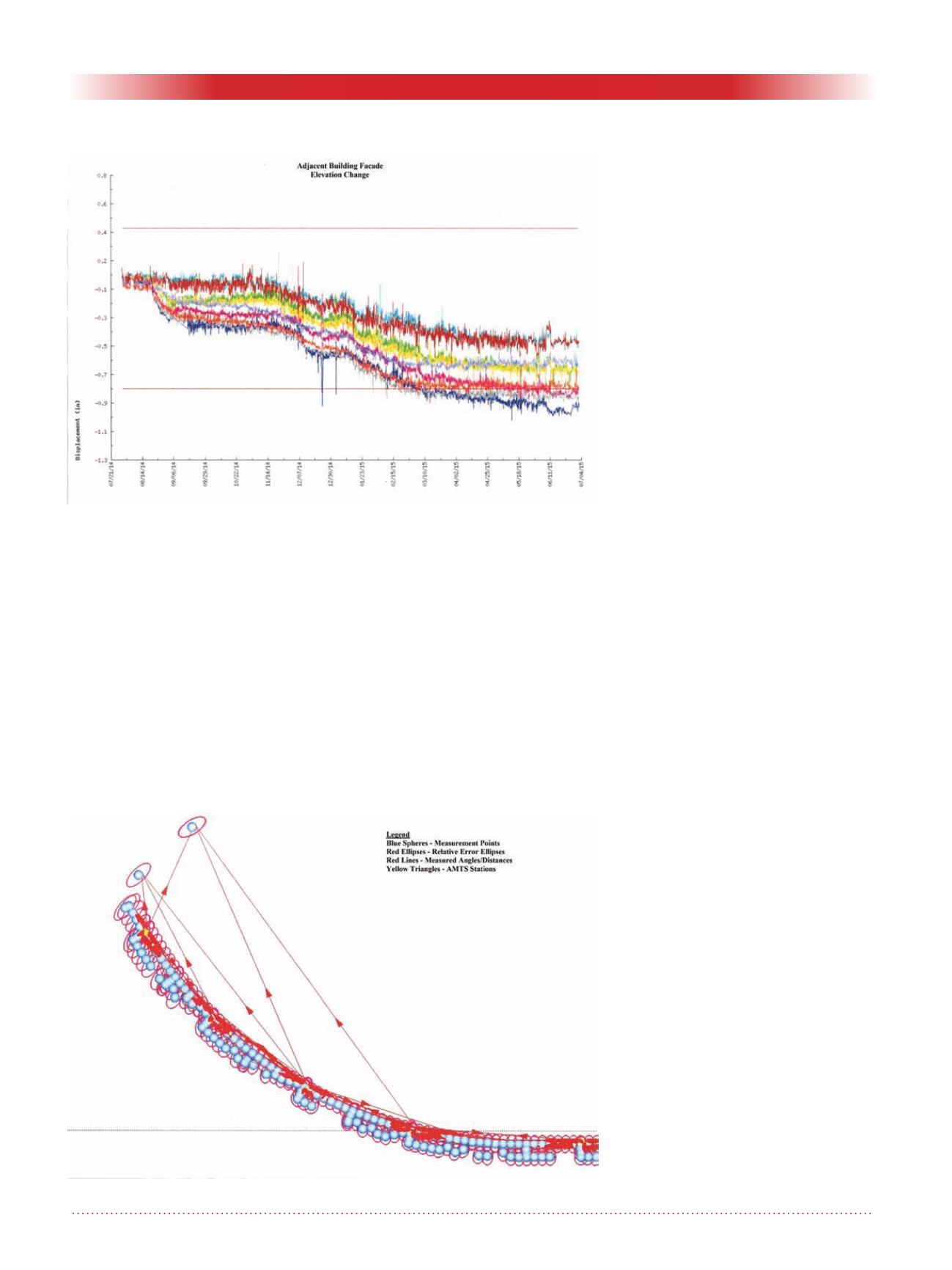
• Review of the data for quality
assurance and identification of
movements and trends as well as
properly identifying possible data
spikes due to transient factors, see
Figure 3.
• Use information from the data
review to refine and adjust the
processing model as needed for
changed conditions in the control
reference frame or environmental
factors.
The direct measurement, taken with
a RTS would be the same whether
programed by a PLS or PE. Much
different then in previous generations
where each measurement was made
in the field by a two man survey crew,
one of which was often the PLS.
Where the Professional (Profes-
sional Engineer or Professional Land
Surveyor) is needed involves how this
resulting measurement is processed,
refined and used within an instrumen-
tation data base. Given the advance-
ments in data processing and database
manipulations that are undertaken
using the least square programs (see
Figure 4), the initial phases of data
base processing of the direct survey
data are more akin to that a profes-
sional mathematician or computer
software engineer. But key to the Pro-
fessionals input is the installed RTS
location(s) and layout to the reflective
monitoring points, confirming that
the measurements between these two
points will give the best quality data,
how corrections to data is undertaken
to correct for various error types, and
of most important how to address
trends or direct movement of points.
In this evaluation the Professional
must also consider the structure being
monitored, its ambient movement as a
result of thermal expansion, the impact
of the movement to the structure and
some of the reasons that movement
may be occurring, such as the excava-
tion or tunnel construction.
RTS construction monitoring does
not include the definition and layout
of boundary lines (property lines),
nor the legal description and convey-
ance of real property. Whereas it
does include the use of highly precise
instruments for the measurements of
Figure 3. Long term monitoring data from a RTS system showing settlement
of a building façade.
Figure 4. Least squares adjustment plot showing relative error ellipses.


